Room-Temperature z-axis focus points on the stage
This following data had been taken using a 250 mm lens on the camera path. They are subject to change from time to time by a little bit, the main point is that you should see the image (of course under the presence of the beamsplitter reflections) around these points, with some image processing on the “ThorcamsImage” software.
| Image focus | 2385 um |
| NIR Excitation | 2413 um |
| Camera lens position | ~250 um |
A question that pops into my head, are the NIR Excitation and Collection the same? If they differ a bit, how is it going to affect us?
The image that we captured using this setting:
Cold Temperature z-axis focus points on the stage
Same explanations as before. One thing to keep in mind is when you just go to the cold temperature, it’s natural for you to not see the image. Be very cautious to change the z-position, as you can’t see if the stages are hitting the sample or not.
| Image focus | 2390 um |
| NIR Excitation | 2410 um |
| Camera lens position | ~250 um |
The image that we captured is shown below:

Although very blurry, at the center you can see a rectangular cavity (L3 cavity) at the center.
Sample with L3 Cavity I-V Curve

For the same amount of current, we had to go to higher voltages in the cold temperature experiment.
Geometrical Optics Analysis with the Distances
We have taken the following data if the distances from the insert and the optical head:
The distance from the objective lens front plane to the camera: 1523 mm + x. This x stands for a variable distance (the last arm in the optical head)
The working distance of the objective lens (WD) = 1.5 mm
The focal length of the objective lens, f = 3.1 mm.
Length of the objective lens = 32.9 mm

The plano-convex lens focal length of the along the path of the white light, f = 40mm.
Geometric optics analysis with the Maryland setup
The focal length of the camera lens, f2 = 40 mm
The image distance from the camera, v2 = 100 mm
From the lensmaker equation, we have, 1/v2 = 1/u2 + 1/f2. So, u2 = -66.67 mm
In the current setup, let’s consider the total length from the front of the objective lens to the camera is ~1693 mm
So, the image distance created by the attocube objective lens is 1693 – 100 – 66.67 = 1526.33 mm
Optically speaking, we can say the image is 1526.33 + 32.9 – (3.1-1.5) = 1559.23 mm away from the sample objective lens.
So for the objective lens, 1/v1 = 1/u1 + 1/f1, u1 = -3.10617
In our case, previously, we kept the stages at z = 2385 um, when the camera was at the focal length of the camera. If now the new distance of the camera is 100 um, the object distance deviation is, 61.7 um. So, in the new focus position, the stage needs to be at around z = 2446.7 um.
Now, from the camera lens, the magnification is, m2 = |v2/u2| ~ 1.5. From the objective lens, the magnification is, m1 = |v1/u1| = 502
The total magnification, M = m2*m1 = 753
Now,the camera has the following specifications:
- 1440 (H) times 1080 (V) pixels
- Pixel size: 3.45 um times 3.45 um
- Width times Height = 5040 um times 3780 um
The lateral field of view is = (5040 um times 3780 um )/753 = 6.7 um times 5.02 um
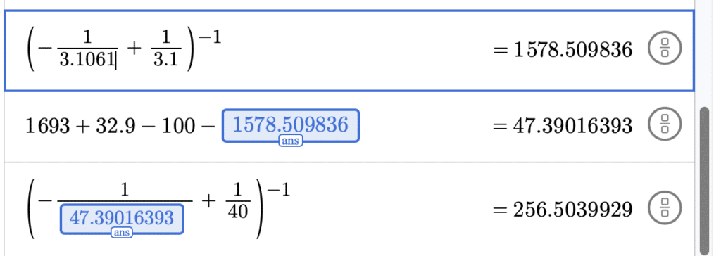
We attach here a Desmos calculator calculation for better understanding the whole process:

Now, let’s omit the last two digits from u1, decrease the distance by 54 nm:

Distance increased by 3mm. Keep in mind that, we won’t be able to fine tune by 54 nm using our stages. Now, we shall do calculation at u1 = -310.61 mm:
And u1 = -310.62 mm:
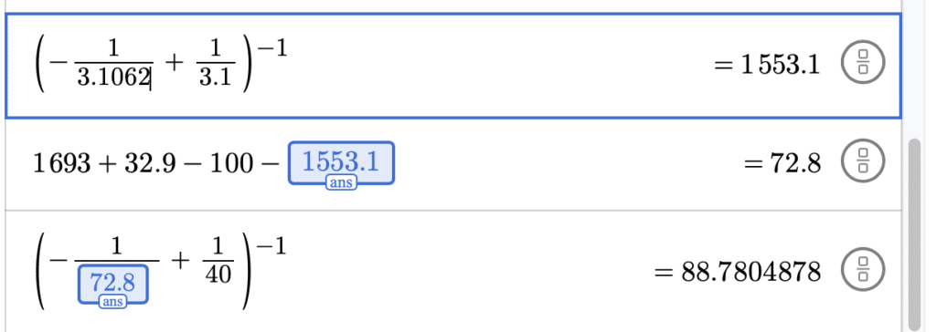
From this calculation, we can say that this setup is pretty sensitive to any disturbance that goes on in the setup, even by 1 um. That’s the lowest that we can change by our micrometer precision stage.