Projects
Current Projects
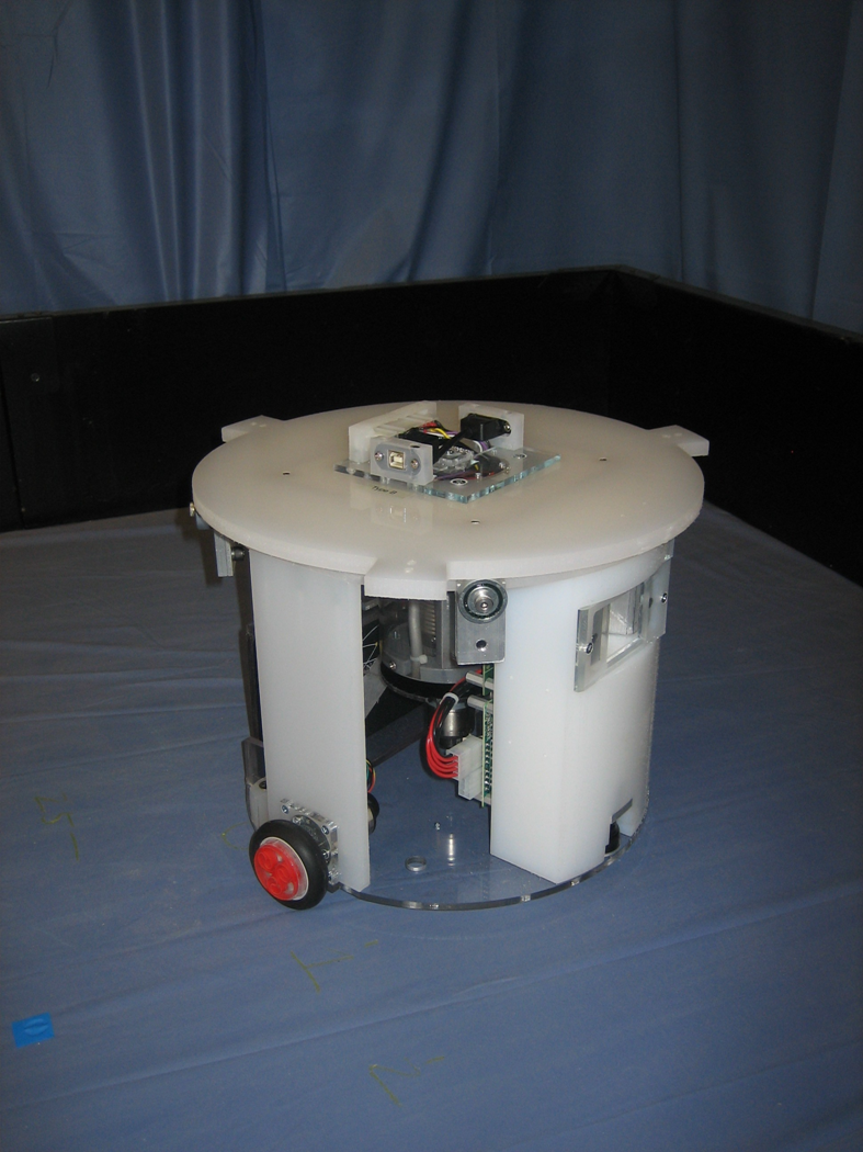
Sensorimotor Integration and its Effects on Adaptive Learning and Control of Autonomous Mobile Robots
Project Leader(s): Matthew D. Craver
Project Researcher(s): Micah Colon, Jim Ashcraft
This research deals with the developmental analysis of robot controllers that are created using evolutionary robotics (ER) methods. ER uses artificial evolution to automatically design and synthesize intelligent robot controllers. An aggregate fitness function that injects relatively little a priori task knowledge into the evolving controllers is used. The course of development of robot controllers evolving to perform a competitive goal-locating task is analyzed. To sample the course of evolution, controllers are taken from progressively more advanced generations, and are tested in a novel environment. Developments and changes in the controllers’ abilities and competencies are identified and correlated with overall controller fitness. As the evolution progresses, the robots evolved more complex high-level behaviors that are not explicitly selected for by the fitness function.
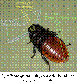
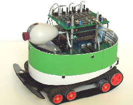
Sensorimotor integration, as it is applied to the ER algorithms that are tested on the Evolutionary Robotic (EvBot) platforms, will lead to greater sensor robustness, emergent intelligence, and autonomous behavior, in a similar manner to that seen in the natural world. The research will be carried out on the new EvBot III, see Figure 1. This autonomous robot platform has been design to have greater synergy between the hardware and the corresponding modular control architecture. Through effective sensorimotor integration, task learning time will Figure 2 Madagascar hissing cockroach with main sensory systems highlighted be reduced, and the learned controllers will be more robust. Also, by combining and correlating multiple sensors and motor states, the system will be increasingly immune to noise and corrupted or missing data from the integrated sensors. These new methods for sensorimotor integration are biologically inspired. Cockroaches, see Figure 2, are chosen as the model for this research. Cockroach behavior and physiology are well characterized, and the cockroach model will be an objective measure for testing EvBot III robustness and its ability to operate autonomously in real-world situations.
Lastly, a modular control environment will speed up new EvBot III sensorimotor element prototyping, evaluation, and portability. The modularity of this new sensorimotor technology will enable systems, like the EvBot III, to adapt to constantly changing environments by integrating the necessary modules that allow the system to adapt to the task. The final system must exhibit robust control and robust behavior, this is critical for real-world tasks.
A Medical Robotic System for Laser Phonomicrosurgery
Current Projects Past Projects
Project Researcher(s): Kent Meiswinkel
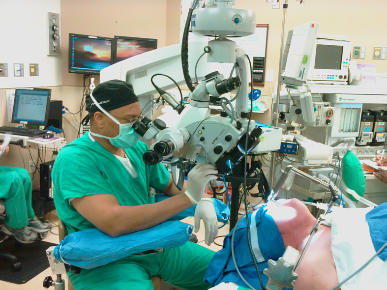
Laser phonomicrosurgery is a demanding surgical technique requiring significant psychomotor skills. Scaleability, operative distance, and the anatomically small nature of the vocal folds all combine to create numerous surgical challenges. Currently the dominant user interface for remotely aiming a CO2 surgical laser is the manual micromanipulator. A micromanipulator is a electro-mechanical device that orientates an optical mirror system to control the aiming of the laser beam to ensure accurate localization on the tissue of interest. This device is capable of accurate laser aiming but is prone to error resulting from inexperience and ergonomic factors. The typical operative setup for laser phonomicrosurgery is depicted in Figure 1.
The mechanical micromanipulator is affixed to the base of the surgical microscope optics and the joystick then extends outward in space beneath the Figure 1 A surgeon using a Photomedix electro-mechanical manipulatormicroscope. The surgeon is required to move the end of the joystick to alter the surgical laser aiming position. There is no physical support available to steady the surgeon’s arms or hands. In addition the joystick itself has limited adjustments for user preferences. It is possible to adjust the resistance to motion via a tension adjustment but this is the only user adjustable parameter. Additionally the operative field for the laser is quite small, on the order of 15-21 mm and the operative distance is 400 mm. As a result very small, precise changes in the joystick position are necessary to accurately alter the surgical laser aiming point. These movements are very difficult to make consistently and are a particular challenge to novice clinicians.
CRIM research has produced a medical robotic system for clinicians practicing laser phonomicrosurgery. This novel medical robot overcomes the problems discussed above. The device employs a classic computer gaming joystick as the user interface and adjusts the surgical laser aiming point in accordance with joystick movements,Figure 2 The CRIM phonomicrosurgery medical robotic system under test Figure 2. The appliance provides for adjusting movement sensitivity and also incorporates a playback function. A playback function allows the clinician to memorize particular target points and then have the appliance repeatedly and accurately position the laser to these points, Figure 3. Active contours have also been integrated into the system allowing rapid definition of excision perimeters which are then employed to automatically aim the surgical laser. Clinical characterization of the system is carried out at the UNC Chapel Hill School of Medicine.
Design of a Wearable Wireless Sensor Network for Continuous Monitoring of the Vascular System
Current Projects Past Projects
Project Researcher(s): Meghan Hegarty, Frederick Livingston
Compression stockings are widely used to treat a number of vascular conditions ranging from tired, aching legs to lymphedema, ulcer and wound care, and prevention of deep venous thrombosis (DVT). Due to the large number of compression stockings available, differences in measurement techniques, etc., finding the ideal compression stocking for a given patient may prove difficult. Improperly fitted stockings can result in inefficient treatment if too loose, or necrosis and pressure damage if too tight.
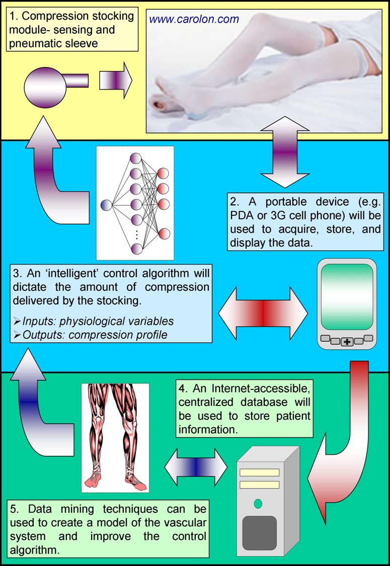
In order to account for differing needs among individuals, a closed-loop control system is proposed whereby the amount of compression delivered by a stocking is altered based upon measured physiological variables, Figure 1. The amount of pressure delivered by the compression stocking is dictated by three, independent, Closed-loop compression therapy modulepneumatically-controlled zones (i.e., these divisions are identical to those currently used in compression stockings). The stocking is meant to be worn with a sensing system. The sensing system currently consists of a portable ultrasound unit for measuring blood flow velocity and a bio-impedance circuit for measuring the degree of lower leg swelling. Future versions of the system will incorporate skin temperature, blood oxygenation, EMG (electromyography), and activity level sensing modules. By measuring changes in the above parameters, we hope to be able to monitor the health of the vascular system.
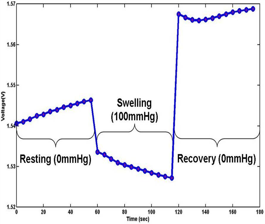
As this project is still largely in the development phase, many of the sensing modules have not been tested outside of the laboratory. To date, small-scale studies have been conducted that indicate a bio-impedance sFigure 2 Results obtained from a bio-impedance system that detects small changes in leg volumeystem is able to detect small changes in leg volume, Figure 2. Ultimately, changes in the measured physiological variables will be used to assess the performance of compression stockings so that corrective actions may be taken (i.e., increase/decrease in applied pressure), thus mimicking what the body does naturally. Not only will such a system reduce the time and cost of treatment, but it will allow for meaningful data to be collected during normal daily activity. This will lead to a better understanding of the vascular system and associated pathologies, as well as enable the investigation of the effects of different pressure profiles.
A Portable Non-Invasive System for Treatment of Chronic Vascular Diseases
Current Projects Past Projects
Project Researcher(s): Frederick Livingston
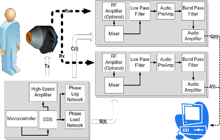
A portable continuous wave ultrasound system is being developed to observer venous and arterial blood flow. This ultrasound system contains an onboard direct digital synthesis (DDS) microcontroller to produces a frequency variable sinusoidal signal. A 5 MHz signal produce by the DDS is amplified, using high-speed op amps, to excite the piezoelectric ultrasound transducer (PZT).
The transmitted signal is reflected by the red blood cells in the vascular system. The reflected signal excites a secondary piezoelectric material producing a low amplitude waveform (receiver signal). The receive signal contains the transmitted signal along with backscattering signals from the motion of the red blood cells. Using a LM1496 Mixer IC, the backscattered signals (Doppler frequency) is isolated from the receiver signals by mixing the transmitted signal with the receiver signals. The Doppler signal is represented by the velocity of blood, speed of sound through body, angle of transmitting element, and angle of receiver element. The filtered demodulated Doppler signals are typically in the audible range and are sent to a remote computer through soundcard for real-time and post evaluation.
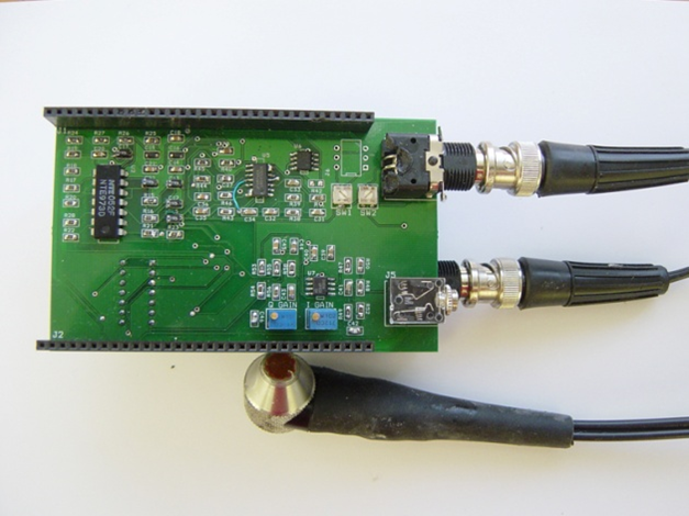
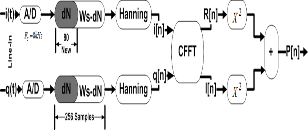
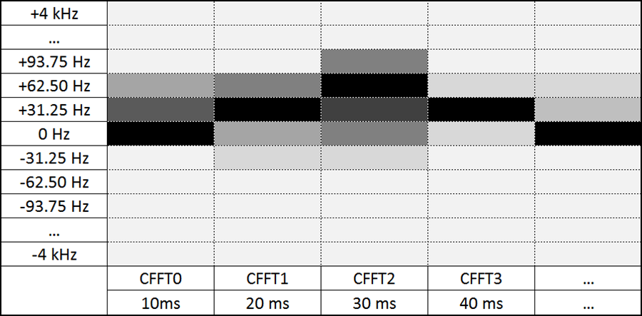
The Doppler signals are sampled by a remote computer sound card at a frequency of 8kHz. Using a Figure 2 The portable Doppler board and probeHanning windowsize of 256 a sonogram was constructed using Complex Fast Fourier Transform (CFFT). Currently the system has problems determining the correct Doppler frequency in human testing. However the system is able to characterize flow rate in a blood mimicking phantom. The problem is believed to do with the angle (θ) in which the probe is applied. The current probes rest comfortable when the piezoelectric elements are 90 degrees to the surface of the skin. This angle drives the above equations to instability. The current research objective is to design and fabricate custom probes to meet the following requirements:
- The probe housing shall rest comfortable on the surface of the skin
- The elements should be position such that they are in an angle with blood vessels
- The probes shall be easily to manufacture
Shape Formation of Robot Swarms
Current Projects Past Projects
Project Researcher(s): Nikhil Deshpande
The idea of multiple robots displaying group behavior has been explored for many years. Group behavior in robots is a desired feature as, for the execution of a particular complex task, it allows for a reduction in the complexity of an individual robot while still exhibiting the same level of group intelligence, required for completing the task itself, e.g., in region exploration task in a search and rescue operation. Similarly, for inspecting rivets on an aircraft fuselage, the shape of the group must be maintained.
A coordinated group of robots can assist rescuers when going into inaccessible areas, e.g., where the terrain is unknown. Having multiple robots will allow the group to spread over a larger region, thus, simultaneously sensing different parts of the region. The group behavior in robots will allow them to move efficiently over the terrain while maintaining proximity and information exchange capabilities. Different approaches exist for the implementation of these group patterns including: (1) biological, and (2) physical. Another artifact of the group behavior is the requirement of some form of communication amongst the robots to maintain group integrity. The recent development in low cost, low power wireless communication technology makes it a prime technology for adopting for sensing and controlling robot swarms. Different features in wireless technologies such as signal intensity and signal quality can now be used to dictate the behavior of the robot group.
The ability of the robot swarm to adapt to the terrain dynamically while still maintaining group integrity is the target of this research into robotic group behavior. In a task such as moving an object through a maze, or a Figure 2 An autonomous mobile sensor platform more natural setting of search & rescue in an unknown environment, a robot swarm shall acquire an optimum shape suitable for Figure 3 Wireless signal intensity calculation tests performed with directional antennas executing the task. While proceeding to execute it, the group needs to sense the obstacles in the environment, adjust the individual positions of the robots to give a different but locally optimal shape to the swarm, then proceed through that location and reconvene into the original optimum shape.
The platforms use wireless technology that includes the MSP430 microcontroller technology with Chipcon radio transceivers for the wireless communication. The robotic platform for the experiments initially involves a simple wheeled vehicle with the attached wireless infrastructure for the control and communication logic.
Past Projects
Wearable Computer Systems
Project Leader(s): Carey R. Merritt
Project Researcher(s):Burcak Karaguzel, Tae-Ho Kang, Anne Jackson
The goal is to integrate circuits into nonwoven textiles to create wearable textile printed circuit boards and systems. This technology will be applied towards wearable computing applications like physiological monitoring garments, textile RFID, and human-robot distributed networks. Our research adopts the technologies used in the polymer thick film (PTF) industry and adapts and applies them to nonwoven textiles. Instead of weaving or knitting conductive yarns with fabrics, we are currently screen printing conductive inks onto novel nonwoven textile substrates produced in the College of Textiles at NC State University.
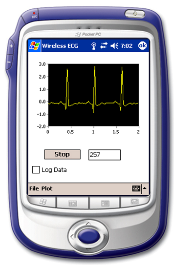
In order to characterize the capabilities of these conductive inks, as they have been printed onto the nonwoven substrates, we have measured the electrical properties of printed transmission lines. These experiments have shown that the printed lines can support multi-gigabit per second applications for line distances of up to 2 meters long. In addition, we have designed active ECG dry electrodes for integration into a garment. Preliminary tests with these nonwoven printed electrodes show promising results yielding a clean ECG waveform. Currently, a wireless Bluetooth system is being developed using a HP IPAQ Pocket PC and a remote embedded Bluetooth system with an ECG preamplifier and Texas Instruments MSP-430 microcontroller. Ultimately, the embedded Bluetooth system will be integrated into a garment for heart rate and respiration monitoring. This system will allow wireless monitoring of a person’s heart rate without large bulky electronics and obstructive wires.
Related projects deal with: (1) the development of unique inductive and capacitive sensors all fabricated on nonwoven textile substrates, and (2) an interactive interface between the wearer and autonomous mobile robots. Outreach to industry includes the following companies and federal agencies: Freudenberg, DuPont™, Creative Materials, Precisia, Paralec, Goulston Technologies, Sara Lee Branded Products, and U.S. Army Natick. This project is funded by the National Textile Center (NTC).
Amorphous Formation Control with Intelligent Competition
Current Projects Past Projects
Project Researcher(s): David Burke
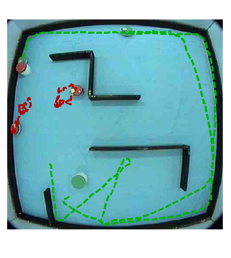
The goal of this project is to establish and control formation movement of an EvBot II colony without explicitly stating which position each EvBot II is to maintain. Each EvBot II will compete for its position in the formation based on an internal heuristic that is a function of: (1) the location of the EvBot II, (2) the desired formation, (3) the proximity of the EvBot II to the formation configuration, and (4) an internal self-diagnostic control algorithm.
The positions within each formation will be ranked from most to least desirable, but the heuristic will be such that a robot that is already near a formation position will compete more fiercely for that position than for any other position. The self-diagnostic algorithm is designed to mimic real world applications where problems could arise that would make the mobile robot less competitive in the formation, such as running low on fuel or taking damage. This heuristic will allow for dynamic changes in the formation while the colony is completing a task. A mobile robot that begins to run low on fuel will begin to lose its competition for its spot and will start to be demoted through the formation. The hope is that if the robot does cease to function then it is already toward the back of the formation where it will hinder the fewest number of other mobile robots in the formation. Conversely, if this algorithm were being used in a military application a damaged robot may be demoted such that it migrates into the center of the formation where it is more protected from enemy fire.
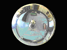
The formations will be maintained through a vision based system where a webcam is pointed upward at a spherical mirror. This gives each robot a distorted three-hundred and sixty degree field of view. Each robot is a different color and knows which color it is so that once the positions are decided a vision recognition algorithm searches the webcam image for the appropriate colors. The EvBot can then determine the angle and the distance to each of the robots in its field of view. These robot locations will be feed directly into the control algorithm to maintain the correct position within the formation. This vision based system allows for greater flexibility since the mobile robots can operate without knowing their global positions in the test world.
Faculty Team: Edward Grant
Phone: 919-515-7016
Emails: daburke@ncsu.edu; egrant@ncsu.edu
Robot Interactions with Randomly Distributed Sensor Networks
Current Projects Past Projects
Project Researcher(s): Kyle A. Luthy, Matthew D. Craver, Leonardo S. Mattos, Blaine A. Levedahl, Micah Colon, T.C. Henderson, Edward Grant
Our goal is to integrate circuits into nonwoven textiles to create textile printed circuit boards. This technology will be applied towards wearable computing applications like physiological monitoring garments, textile RFID, and human-robot distributed networks. Our research adopts the technologies used in the polymer thick film (PTF) industry and adapts and applies them to nonwoven textiles. Instead of weaving or knitting conductive yarns with fabrics, we are currently screen printing conductive inks onto nonwoven textile substrates.
In order to determine the capabilities of these inks as they have been printed onto the nonwoven substrates, we have measured the electrical properties of printed transmission lines. These experiments have shown that the printed lines can support multi-gigabit per second applications for line distances of up to 2 m. In addition, we have designed active ECG dry electrodes for integration into a garment. Preliminary tests with these nonwoven printed electrodes show promising results yielding a clean ECG waveform. Currently, a wireless Bluetooth system is being developed using a HP IPAQ Pocket PC and a remote embedded Bluetooth system with an ECG preamplifier and Texas Instruments MSP-430 microcontroller. Ultimately, the embedded Bluetooth system will be integrated into a garment for heart rate and respiration monitoring. This system will allow wireless monitoring of a person’s heart rate without large bulky electronics and obstructive wires
Our outreach to industry currently includes the following companies: Freudenberg, DuPont™, Creative Materials, Precisia, Paralec, and Goulston Technologies. This project is funded by the National Textile Center (NTC).
Learning and Control of Autonomous Mobile Robot Colonies
Current Projects Past Projects
Project Leader(s): Matthew D. Craver
Project Researcher(s): Micah Colon, Jim Ashcraft
Current work focuses on determining methods of integrating multiple diverse sensors, and corresponding motor states, into a unified framework for learning and control. Initial implementation will be performed on the EvBot II robotic platform. Through effective sensorimotor integration, learning time will be reduced, and the learned control systems will exhibit more robustness of control and increased generalizability. Also, by combining and correlating multiple sensors and motor states, the system will be increasingly immune to noise, and corrupted or missing data from the integrated sensors.
In addition, work is being done to expand the sensorimotor integration to include sensors residing on other robots in the colony, and from surrounding independent sensors that make up a distributed sensor network. Using sensors on other robots in the colony and the distributed sensor network enables the EvBots to maintain a common expanded knowledge of the environment in which they are interacting. This is essential for effectively coordinating efforts between distributed, possibly diverse, groups of autonomous robots.
In order to facilitate this full and complete sensor integration, a modular control environment is being developed. This modular control environment will increase the speed and ease with which new sensorimotor elements can be prototyped and evaluated on the mobile robotic platform. Due to its modular nature, this control environment will be easily portable to different robotic, or simulation, platforms.
The combination of these resulting technologies will enable the autonomous robotic system to adapt to constantly changing environments and sensorimotor systems. Such a system will exhibit the necessary robustness of control and behavior that is critical in real world situations and environments.
Evolution of Complex Autonomous Robot Behaviors Using Competitive Fitness
Current Projects Past Projects
Project Researcher(s): Andrew L. Nelson, Greg Barlow, John Galeotti, Stacy Rhody
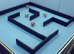
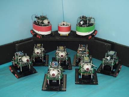
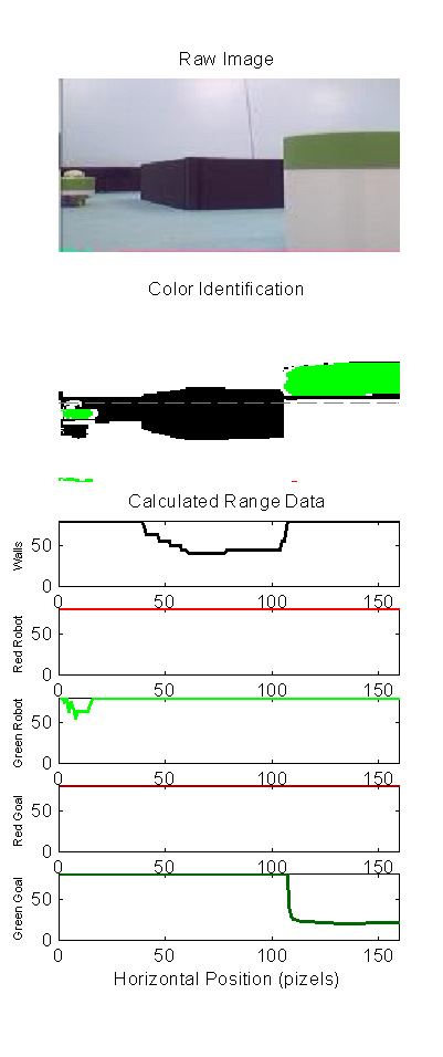
Evolutionary robotics (ER), a sub-area of cognitive robotics, employs population-based artificial evolution to develop behavioral robotics controllers. The research was conducted using the CRIM’s EvBot 1 and EvBot II colonies of autonomous robots, Figure 1. This research focuses on the formulation and application of a fitness selection function for ER that makes use of intra-population competitive selection, based on range sensor data, Figure 2, and genome mutation, Figure 3.
In the case of behavioral tasks, such as game playing, intra-population competition can lead to the evolution of complex behaviors. In order for this competition to be Figure 2 Range Sensor Emulation realized, the fitness of competing controllers must be based mainly on the aggregate success or failure to complete an overall task. However, because initial controller populations are often sub-minimally competent, and individuals are unable to complete the overall competitive task at all, no selective pressure can be generated at the onset of evolution (the Bootstrap Problem). In order to accommodate these conflicting elements in selection, a bimodal fitness selection function is formulated. This function accommodates sub-minimally competent initial populations in early evolution, but allows for binary success/failure competitive selection of controllers that have evolved to perform at a basic level.
Here, large arbitrarily connected neural network-based controllers were evolved to play the competitive team game.Results show that neural controllers evolved under a variety of conditions were competitive with a hand-coded knowledge-based controller and could win a modest majority of games in a large tournament
Automated Cell Microinjection
Current Projects Past Projects
Project Researcher(s):Leonardo Mattos
The goal of the research project is to increase the consistency and efficiency rates for the microinjection of embryonic stem cells into blastocysts through automation and development of an intelligent control strategy.
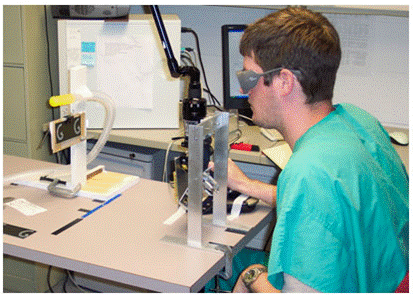
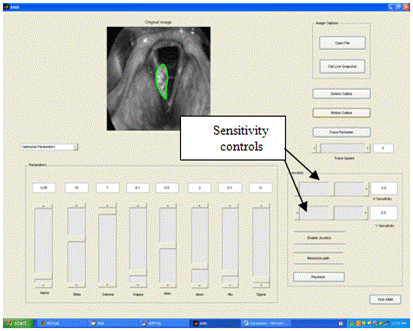
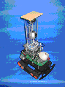
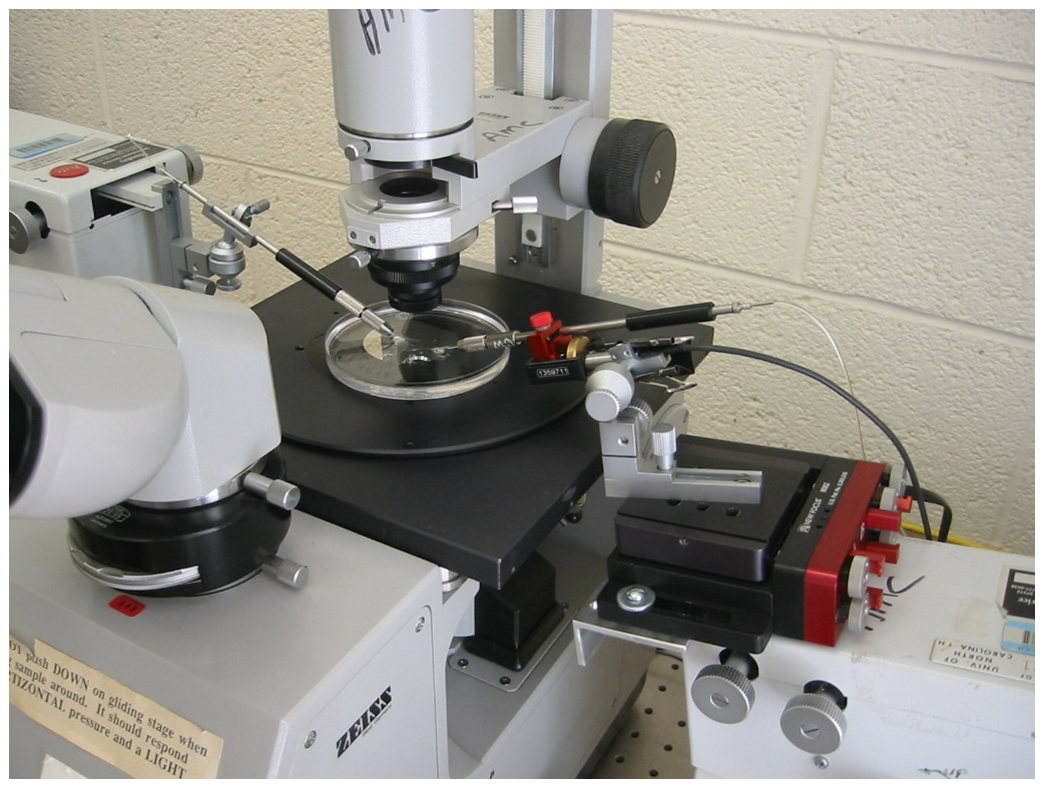
Interaction with the Animal Model Core Facility at UNC-Chapel Hill showed that cell micro-injection systems needed transformation, from a manual, time-consuming, and tedious, micro-injection process to an automated process. As a first step towards achieving full automation we have assembled a system that is semi-automated. The major feature of our semi-automated system is an interactive user interface, one that treats the cellFigure 1 A semi-automated cell micro-injection system microinjection process like a computer game. From the strategies adopted by many players we will devise a controller based on the experimental results and machine learning techniques.
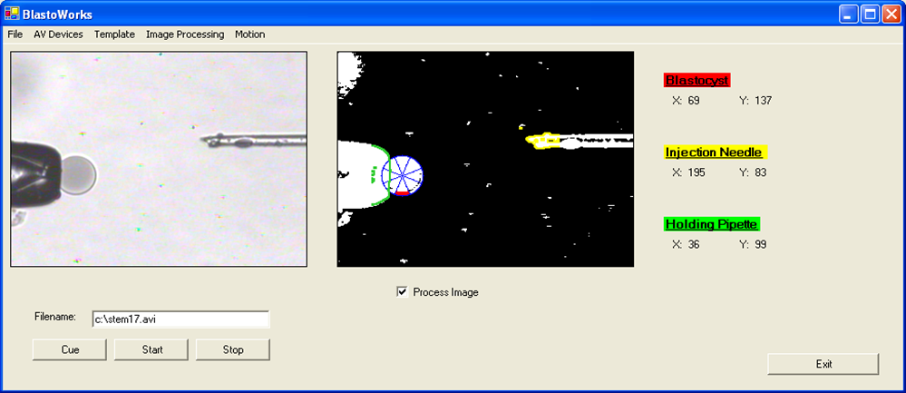
In Figures 1 and 2 the system for positioning the injection needle under user control is displayed, using a joystick. Figure 3 shows how video processing software was developed to find a blastocyst, and how to manipulate and record the position and orientation of the blastocyst using the injection needle. The goal is to have the blastocyst located at the holding pipette with the inner cell mass positioned at 180 degrees from the stem cell injection needle.
Tests showed that an expert could improve their rate of successfully injecting cells, from 40%-70%, to 80%. More, a novice, with no knowledge of cell in vitro fertilization could also get 80% success with two days training on this system.
Electronic Textile-Based Sensors and Systems for Long-Term Health Monitoring
Current Projects Past Projects
Project Researcher(s):Carey Merritt
Personalized long-term health monitoring has the potential to improve medicine’s capabilities for diagnosing and correctly treating diseases at an early stage. Here, electronic textile based sensors were designed and fabricated to measure ECG and respiration. Recommendations are made for developing an unobtrusive, wireless, health monitoring garment. Wireless sensor networks (WSN’s) provide unprecedented spatial and temporal sensory resolution.
Two versions of fabric based active electrodes were designed and fabricated for use in ECG monitoring, Figure 1 and Figure 2. In the first active electrode, surface mount components were attached directly to a textile substrate; using a screen printed circuit and polymer thick film ink. The second ECG system used an interposer board, to simplify the electronic textile circuit. These two ECG systems gave results that compared favorably to results obtained from commercially available Ag/AgCl electrodes. The interposer system even survived a five cycle washing test.
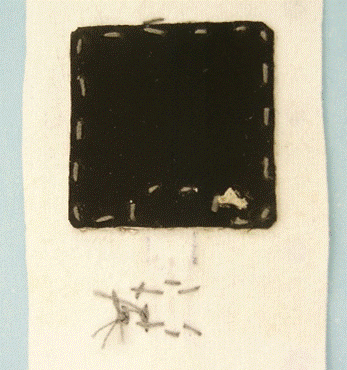
This research also explored the use of capacitive sensing for long-term respiration monitoring, Figure 3. Capacitive sensors were designed and fabricated to detected chest or abdominal circumference changes. These capacitive sensors gave good linearity, sensitivity, and resolution. Respiration measurements obtained with these new sensors were integrated into a prototype belt. Tests show that they are capable of measuring respiration rate, and possibly lung function parameters too.
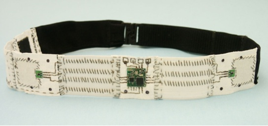
Lastly, a new modular wireless sensor node (MWSN) system for wearable health monitoring is presented, Figure 4. Experiments show that the MWSN is capable of interfacing to a wide range of health monitoring sensors while maintaining signal fidelity, Figure 4. This research was funded by the National Textile Center (NTC).
Methods of Analysis for Musculoskeletal Systems
Current Projects Past Projects
Project Researcher(s):John Kelly
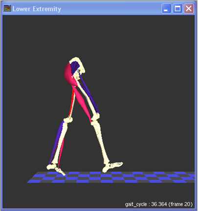
The first part of this project involves an investigation of current musculoskeletal modeling techniques and an attempt increase the accessibility and visibility of these techniques to clinical researchers. There are many software packages available for analyzing motion capture data, but a lot of researchers are forced to write their own software due to compatibility problems or prohibitive costs.
The top priority is determining the accuracy of data generated by various software packages, which will be done at UNC with Visual3D and MotionSoft, and at NC State with OpenSim (Figure 2), SIMM (Figure 3), and the AnyBody Modeling System. These tests can only be completed after creating software for data format conversion between common motion capture system formats and common motion analysis system formats. In the end, this will also help improve accessibility to these software packages and ease collaboration between laboratories.
VicoFigure 2 Lower body model in SIMM data at UNC has already been processed in Matlab and translated to formats that are easily usable by the SIMM and OpenSim systems. If OpenSim produces accurate results, it is desired to be able to import data into it, due to it being freely available and having an active development community. Current results seem promising for importing and analyzing motion capture data recorded by markers, but there have been greater errors in importing ground reaction force data from force plates.
The second part of this project uses pattern recognition techniques to classify the conditions of patients performing tasks in a virtual reality environment. As a proof-of-concept, data that was recorded on some healthy patients and on some patients who have suffered a stroke will be automatically classified in order to identify if a patient has abnormal mechanics in their motion. Although this is a diagnosis that can be made fairly easily by a clinician, it is hoped that any developed techniques and feature spaces used for classification can later be expanded upon to help make more difficult diagnoses.
A Bio-modeling Investigation of Bracing on Clubfoot
Current Projects Past Projects
Project Researcher(s):Andrew DiMeo
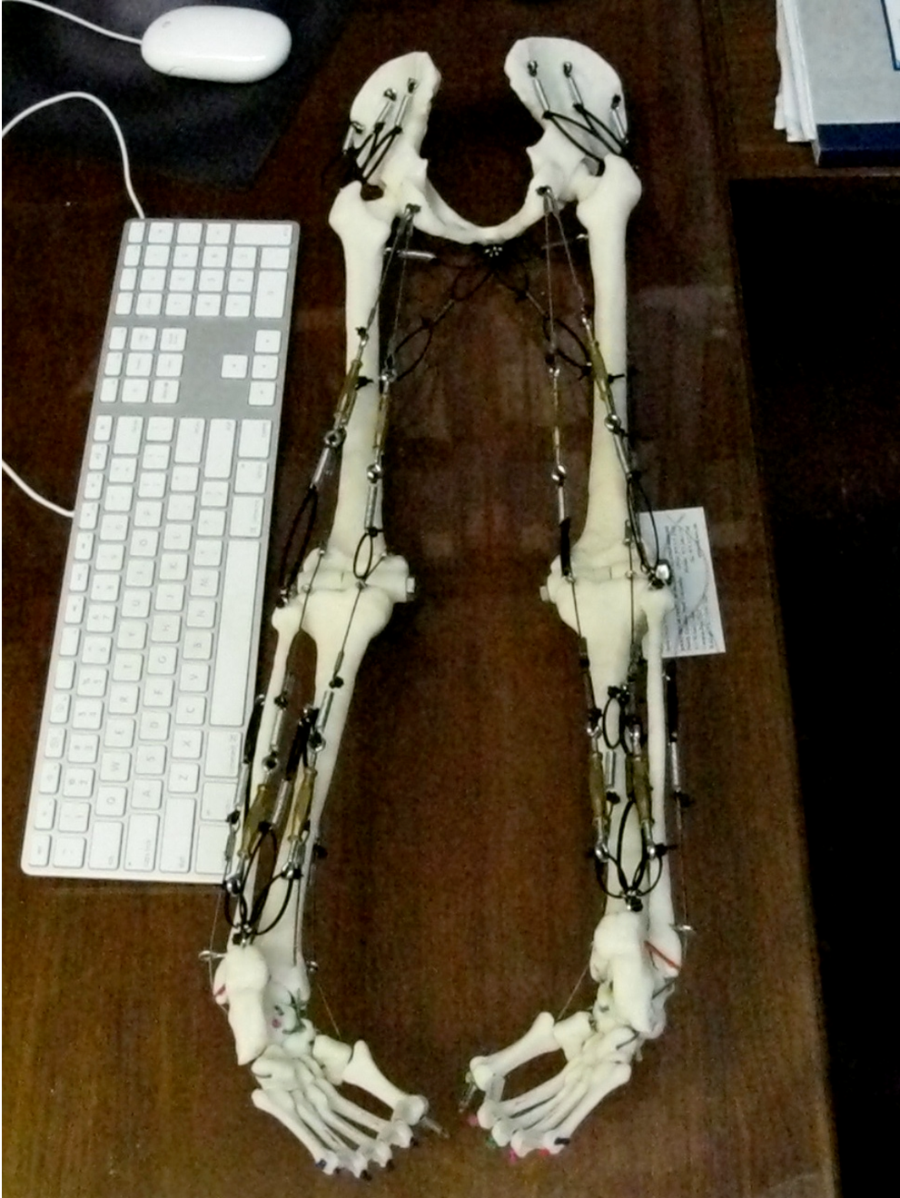
Congenital talipes equinovarus, commonly referred to as clubfoot, is a complex deformity that occurs in an otherwise normal child. It presents in utero bilaterally or unilaterally with the affected feet completely turned inward. Clubfoot is the seventh most common congenital birth defect, and the first most common musculoskeletal birth defect, occurring in about 150,000-200,000 babies each year worldwide. In addition to its congenital presentation, clubfoot can also accompany such disorders as Spina Bifida and Arthrogryposis [18]. Despite extensive research, the etiopathogenesis of clubfoot remains unknown. Regardless of the method of treatment, whether surgical or conservative, clubfoot has a stubborn tendency to relapse. Nearly all forms of treatment prescribe bracing to prevent relapse. While surgical and conservative treatments can last months after birth, brace wear is often maintained until a child is between three and five years of age.
A survey of the literature reveals extensive research over the last fifty years concerning the pathology of clubfoot and surgical versus conservative treatment of clubfoot. In contrast, while bracing is a topic that appears across such a survey, there are no investigations that are specifically focused on clubfoot bracing from an engineering perspective. One significant outcome of this research is the development of a clubfoot brace test method and apparatus (the surrogate biomodel) that provides accurate and rFigure 2 A close-up of the clubfoot condition on the biomodelepeatable results. For example, the results of current testing can be compared to the braces currently considered the standard-of-care. Such testing provides useful clinical information. For example, there are many alternatives to the standard-of-care brace and many adjustments that can be made to all braces, including parameters such as brace width, abduction angle, and dorsiflexion angle. An alternative brace configuration is one that allows motion (such as the Dobbs brace). This research provides information on how the standard-of-care and alternative braces stretch measured muscle-tendon systems, and how changing the parameters of each brace will affect that stretching.
The specific aims of this research are to:
- Build a surrogate biomodel of human pediatric lower extremity anatomy, see Figure 1 and Figure 2.
- To compare various clubfoot brace configurations within one brace type.
- To compare different brace types.
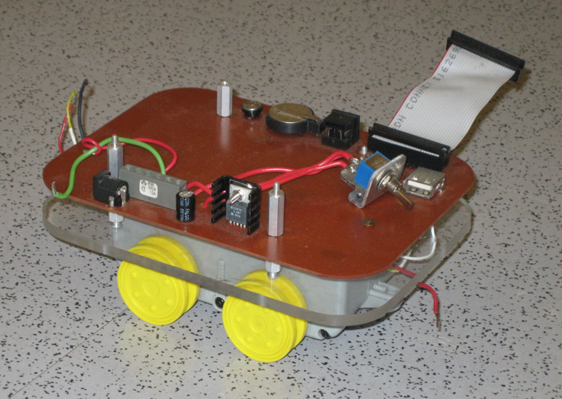
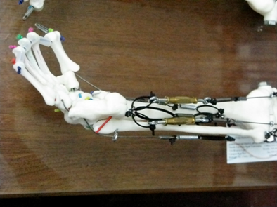
Robotic Navigation and Repair of Wireless Sensor Networks Using Received Signal Strength (RSS)
Current Projects Past Projects
Project Researcher(s):Kyle Luthy, Nikhil Deskpande
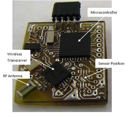
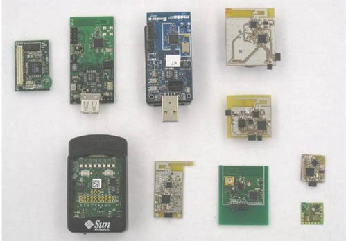
Wireless sensor networks (WSN’s) provide unprecedented spatial and temporal sensory resolution. The ubiquity of wireless sensor networks is made possible by their small size, Figure 1. These devices have remarkably low power consumption and once powered up, can operate without service for months, or years.
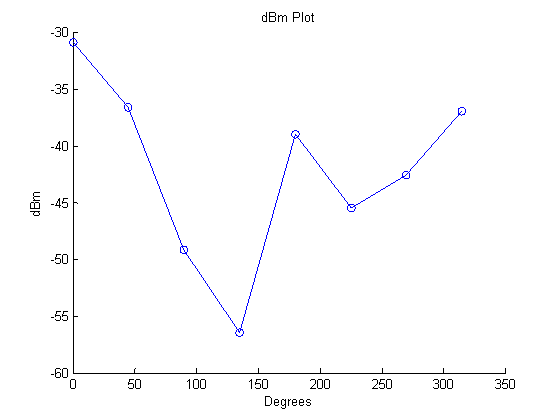
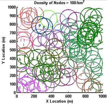
CRIM WSN’s research looks at large area applications requiring hundreds or thousands of nodes, i.e., for monitoring for wildfires, search and rescue tasks, and battlefield information gathering. For these situations it is not practical to optimally hand place each node, therefore an air-drop will be used to distribute the nodes. As the nodes become active, they will form an ad-hoc networks. Due to the random nature of their deployment several network clusters will be formed, Figure 2. Each node is Figure 2 Network clusters formed by randomly distributing 100 nodes over a square kilometerspecified by a letter or number with its communication range denoted by the colored circle surrounding it. Like colors represent node clusters that can communicate with one another. As more nodes are dropped, these networks will become connected but there is a point of diminishing return where the addition of numerous nodes will be needed where a few intelligently placed nodes would have been adequate to connect the disjoint networks.
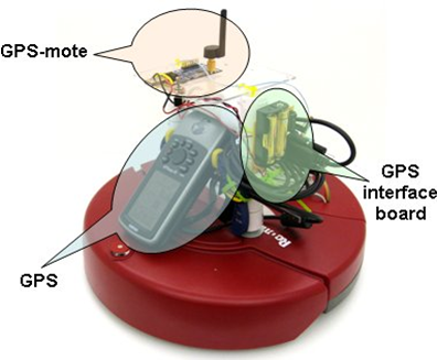
Determining how to connect these networks is an interesting problem as there is little to no information regarding the location of the nodes within the deployment area. This research uses an autonomous robot, equipped with a radio, such that it becomes a mobile sensor node, Figure 3. By monitoring the communication signal strength between itself and any nodes in its broadcast range, the robot “ski’s” through a network cluster in search of a connection point and connects to other clusters. The robot adjusts its performance to deal with obstacles in its communication range. Upon completion of the repair task, the robot has improved network efficiency and coverage, and has reduced the number of required nodes by a factor of 10.
Wall Attachment Robots for Sculpted Surface Inspection
Current Projects Past Projects
Project Researcher(s): None Listed
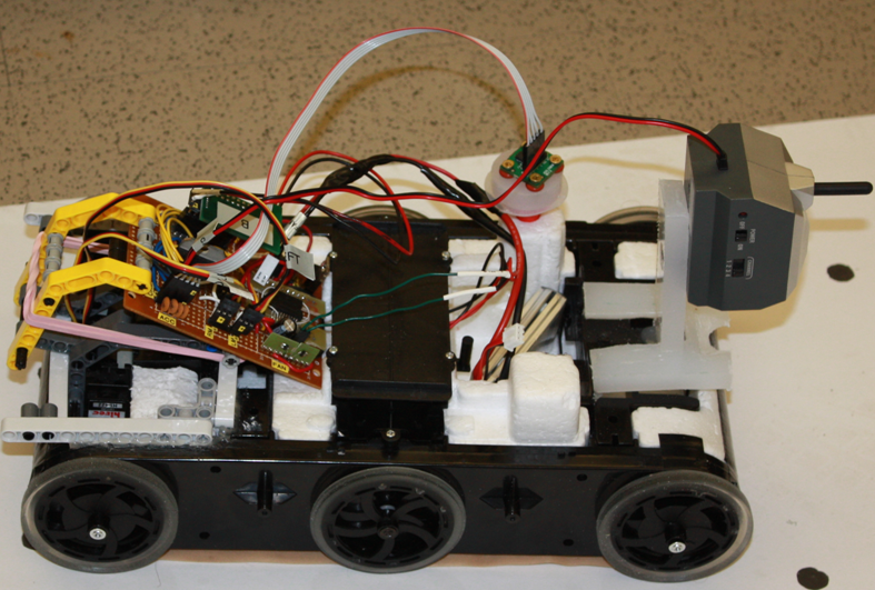
A proof of concept project was devised that produced an autonomous wireless mobile robot platform for sensing, locating, and inspecting a line of rivets. More, the robot system had to adhere to an aircraft surface when at a high degree of tilt angle, it needed to posses wall adhesion capabilities. Early on a decision was made to use the MSP430 MCU and the CRIM-mote design as the basic sensing and control technology on the robot system, since the CRIM is experienced with this processor and the learning curve was minimized by using this technology. Next, a literature search produced examples of autonomous wall crawling robot platforms. An Internet search revealed a possible robotic platform solution, a low-cost out of the box radio controlled mobile car that was capable of adhering to a vertical wall. RC cars were purchased and they became the basis of the autonomous wall attachment robotic system. Suction is created on the underside of the chassis by a Venturi vacuum, this suction is strong enough to hold the RC car to a vertical wall. The box system RC system was modified to give autonomous control, and in particular for crawling on a vertical wall, see Figure 2.
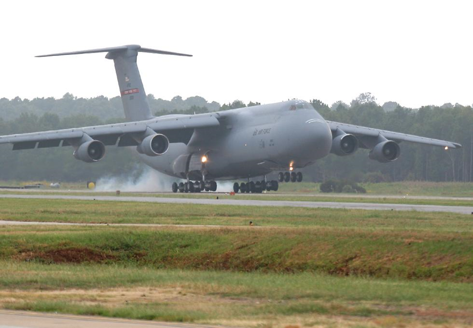
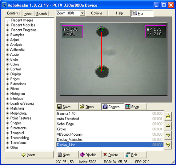
A camera was the sensor of choice for locating the simulated rivets in the demonstrator. Aircraft rivets are aluminum, and are on sculpted surfaces (Figure 1), so a Hall effect sensor was inappropriate for detecting river faults and controlling the robot under development. And, since rivets are generally circular and circles can easily be found using image processing a camera was chosen to detect rivet faults and for navigation between rivets, or a line of rivets. In choosing the camera it was decided to do all the heavy image processing computation locally, on a powerful computer suited to the task. For this reason the mote had to be taken out of the feedback loop. A camera with a 2.4 GHz transmitter and receiver seemed to be the best solution and this was mounted onto the platform. Now, all the decentralized processing and the video from the robot were transmitted to a remote computer, one with significantly more calculating power than the onboard processor could handle. A desktop computing platform, running Matlab – a mathematics software suite – and RoboRealm, a computer visioning application to handle our controls.
Video is streamed over a dedicated 2.4GHz channel from the robot directly to the computer, to be analyzed by RoboRealm, Figure 3. RoboRealm processed the image information to determine the location of circles relative to the x-y coordinate system of the camera image frame. RoboRealm then feeds a data stream of directional information to Matlab. When the program is in automatic control mode Matlab, using the RoboRealm data stream and PID user input from a custom Matlab GUI, auto-generated the left and right PWM values for the robot. When Matlab was in manual mode, the user controlled the robot via the custom GUI. The GUI both sends data and receives data from the robot. The GUI queries the 3D accelerometer axes values (tilt angle) of the robot to control the vacuum system.