Lab Facilities
In preparation for commissioning of the series inverters for the NYPA CSC project additional testing on the Transient Network Analyzer (TNA) was performed.
The additional tests are referred to as sequence tests because the aim was to thoroughly examine the control system for areas such as starting, stopping the equipment, and changing between configurations and for behavior during trip conditions.
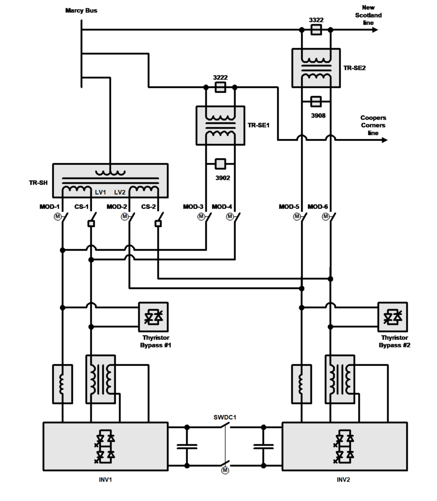
CSC TNA One-line diagram
The CSC TNA model comprises two voltage source inverters (Inverter #1, Inverter #2) interfaced to the power system with coupling transformers, as illustrated in Figure 6‑1. A dc bus switch (SWDC1) is provided so that the inverters can be operated either independently of each other (dc switch open). Alternatively, the dc switch may be closed to allow exchange of real power between the inverters. Switches are also provided so that the ac output of each inverter can be connected to the power system in two different ways.
For shunt compensation, Inverter #1 and Inverter #2 can be connected to LV1 and LV2 respectively, which are the secondary windings of the shunt-coupling transformer (TR-SH). For series compensation, Inverter #1 can be connected to the series insertion transformer for the Coopers Corners line, and Inverter #2 can be connected to the series transformer for the New Scotland line.
The TNA one-line closely resembles the one-line of the actual power circuit. Some elements are not modeled
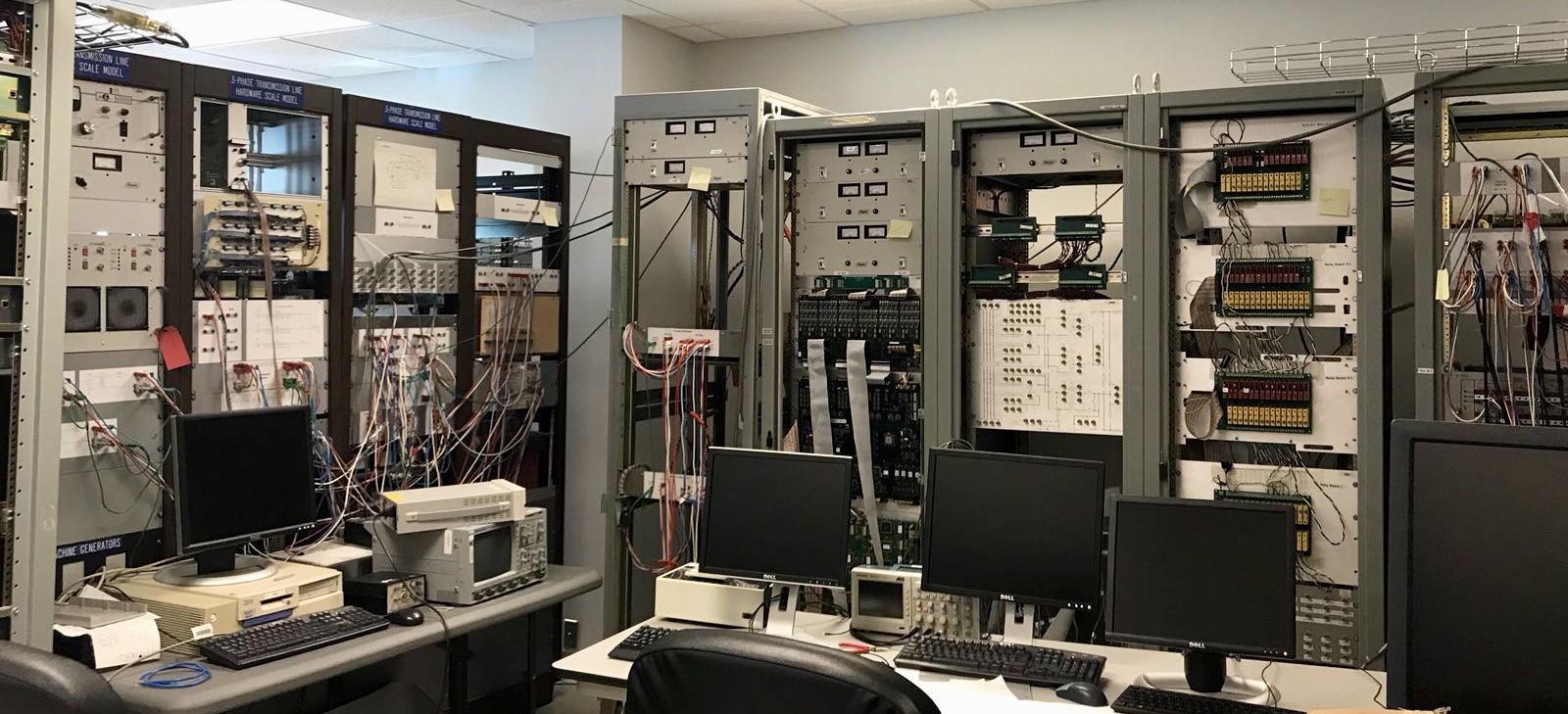
CSC TNA Hardware
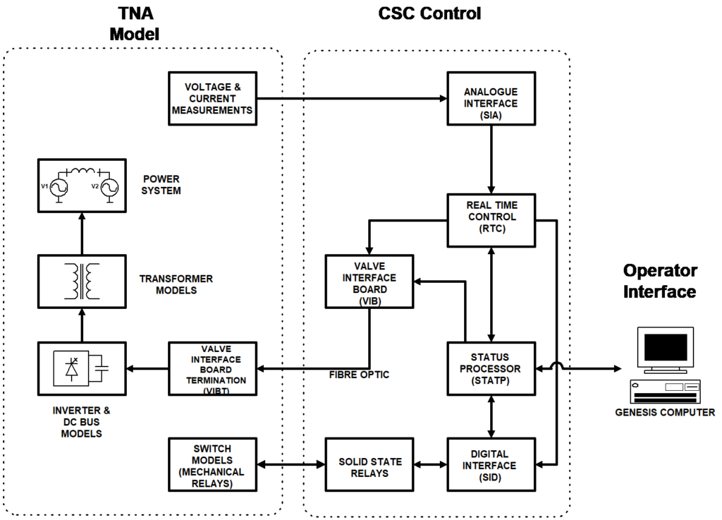
A small-scale analog model of the equipment represents the switching nature of the inverters as well as the nonlinear characteristics of the coupling transformers. The actual control boards were interfaced to the analogue equipment model to test the CSC control algorithms (implemented in the DSPs of the RTC) in a real time environment. This real time testing is especially important in a project such as this with its multiple equipment configurations and various control modes. Successful testing on the TNA provided a high degree of confidence that the series control modes would perform as expected when commissioned at site.
The TNA model for the CSC is a scaled analogue equivalent model of the actual transformers, switches, and inverter equipment connected to the CSC central controls. The nominal inverter rating of 100 MVA is scaled to 12 VA and the nominal system voltage (345 kV) is scaled to 100 V. The transformer models (magnetics) are specially designed to represent the per unitized saturation (knee point and slope) and leakage reactance of the actual transformers. Special care is taken to minimize resistive losses and to minimize as much as practical stray inductance and stray capacitance. The transformer models are sufficiently flexible to allow turns ratios, saturation and leakage characteristics to be adjusted.
The inverter valves and thyristor bypass circuits are represented with low loss FET switches. Switching commands are sent from the central control Valve Interface Boards (VIB) over a fiber optic link to the Valve Interface Board Termination (VIBT). The VIBT is specific to the TNA model. In practice, the fiber optic cables would be terminated on individual Pole Electronics Boards (PEB) in the inverter hall.
The MODS, circuit switchers, and circuit breakers
Control Modes
To cover the requirements for the eleven possible circuit configurations, each inverter has four basic control structures available for selection:
STATCOM CONTROL. For shunt operation of the associated inverter. The reactive output current of the inverter is regulated to maintain a desired ac bus voltage. The real (power) component of output current is controlled indirectly to maintain the necessary level of dc bus voltage.
SSSC CONTROL. For stand-alone series operation of the associated inverter. The inverter output (series injected) voltage is controlled to be in quadrature with the prevailing line current and have a desired magnitude.
UPFC SERIES INVERTER CONTROL. For the case where the associated inverter is the series element in a UPFC configuration. The inverter output (series injected) voltage is controlled to influence the line power with no restrictions on phase of the injected voltage.
IPFC CONTROL. For operation of the associated inverter as one element of an IPFC configuration. The output (series injected) voltage of the inverter is controlled to influence the line power subject to the restriction that real power must not be exchanged with the line unless it can be balanced by the power exchanged by the other inverter.
Power System Modeling
The CSC interface to the power system model for the NYPA equivalent system is shown in Figure 6‑3.
Three high power 3-phase amplifiers are used to represent system voltage sources at the major busses. The magnitude, phase, and degree of unbalance are controlled through a separate computer interface. The voltage sources are adjusted to establish power flows in the network. A thyristor switch is used to apply bus faults; the fault impedance, type (e.g. single phase, 3 phase), and bus location are controlled by manual ‘dip’ switches. The incidence angle and duration of the fault are controlled by the computer interface.
Source and transfer impedance are selected so that the short circuit levels at the three busses of interest i.e. Marcy, New Scotland, and Coopers Corner are close to the real system. PI section models represent Cooper Corners and New Scotland transmission lines. There are two switched capacitors representing the 200 MVAR capacitor banks at Marcy. The power system model is very flexible. Transfer impedance, load models, and PI section transmission models can be easily configured manually with ‘dip’ switches. All components are modular and can be readily reconnected with banana plug test leads. Therefore, it is easy to change the network configuration or component values.


Figure 6-3 NYPA TNA Setup
Circuit Topology

Using the latest silicon carbide devices, this test circuit is rated for 1700 VDC and 75 A, providing a wide range of characterization capabilities. With two stages, the circuit can provide true ‘flat top’ trapezoidal current. It can also provide multiple slope excitation as seen in multiport dual active bridges, volts / turn mismatched active bridges and a variety of other test circuits. Multiple low voltage side converters can be paralleled to provide nearly infinite possibilities including sinus / resonant excitation at switching frequencies, quasi resonant and DC offset excitations with minimal filter requirements. Initial research has focused on characterizing soft magnetic material where we found traditional techniques can lead to measurement errors between -38% to 400%. Our work has contributed to the National Energy Technology Laboratory soft magnetic material data sheet development: netl.doe.gov/TRS
Example Trapezoidal Excitation

Voltage and current for dual slope excitation emulating a DAB

Hysteresis loops using accurate characterization, Vtr, and traditional, square excitation, techniques
Relevant Publications
- R. Beddingfield, S. Bhattacharya, D. Storelli, Circuit for Providing Variable Waveform Excitation, Provisional Patent: 98192/1063283, 62/583,843, November 10, 2017, United States
- R. Beddingfield, P. Vora, D. Storelli and S. Bhattacharya, “Trapezoidal characterization of magnetic materials with a novel dual voltage test circuit,” 2017 IEEE Energy Conversion Congress and Exposition (ECCE), Cincinnati, OH, 2017, pp. 439-446.
- R. Beddingfield, S. Bhattacharya, “Multi-parameter Magnetic Material Characterization for High Power Medium Frequency Converters”, The Materials, Metals, & Materials Society (TMS) Supplemental Proceedings, 2017, 693-708
- R. Beddingfield, D. Storelli and S. Bhattacharya, “A novel dual voltage source converter for magnetic material characterization with trapezoidal excitation,” 2017 IEEE Applied Power Electronics Conference and Exposition (APEC), Tampa, FL, 2017, pp. 1659-1666.
Collaborators


This technical effort was performed in support of the National Energy Technology Laboratory’s ongoing research under the RES contract DE-FE0004000.
