


Sensor Networks
A Personal INdoor Sensor (PINS) network is a wireless sensor network deployed in-homes or in-buildings to monitor the indoor conditions and the humadaily behavior. Sensor nodes are usually equipped with passive infrared (PIR), temperature, acoustic sensors that can capture unpredictable conditionand behaviors. Nodes communicate via wireless links in a multi-hop fashion. Placement/orientation of these sensor nodes should be carefully designeto sense entire field of interest.
Objectives
Indoor environments have several challenges in terms of wireless communication and sensing. In this research, our objective is to investigate thproperties of indoor environments for wireless sensor networks. This would be veruseful since home itself is like a living organism. Furniture might move, peoplmight start to emit noise at certain hours, heat can change etc. Further, transmission and sensing coverage in indoor environments should be studieby an experimental study to capture the irregularity due to many obstaclesWe will further implement and test our algorithms to improve the reliable communication and event detection for several applications.
Potential Applications
PINS network composed of PIR supported motes can be used in variety of office (workplace) and home applications. Similar to the context-aware ho projects, PINS network can easily be deployed for human tracking for health car daily life monitoring, energy management (light, A/C turn on/off) etc. In such applications, benefits of PINS would be summarized as follows:
- adaptable to existing building with minor construction and maintenance
- low-cost
- ubiquitous
- customizable based on the life style (workplace, home for elder people, children house, etc.)
- can be improved to act as an emergency system
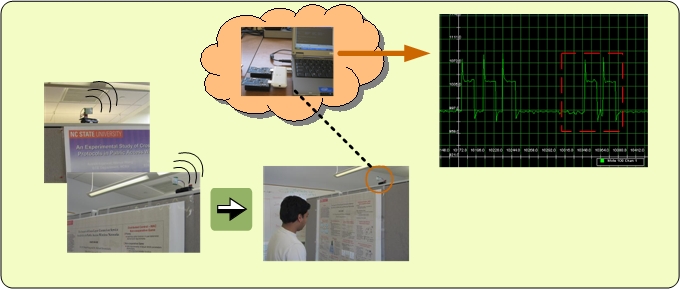
An example monitoring application of PINS isexhibition monitoring. Especiallin art exhibitions, it is very helpful to have the statistics of the numbeof visitors per each painting. Using a PINS network, sensor nodes that arplaced to monitor each painting may detect each visitor in front of the paintinand inform the base station in multi-hop fashion. Such information is alsvery critical from the designer point of view working on the visibility of each painting. We placed the sensors to detect the number of visitors for our research posters as shown below.
PINS Network Setup
For our testbed, we have deployed 18 Tmotes to our lab. Some of our Tmotes have PIR sensors visually (or virtually) tracking the people's daily interaction with their habitat and monitoring the indoor conditions. To track the people in an indoor environment, we use PIR sensors. Detailed explanation on our experiments and findings will be available soon.
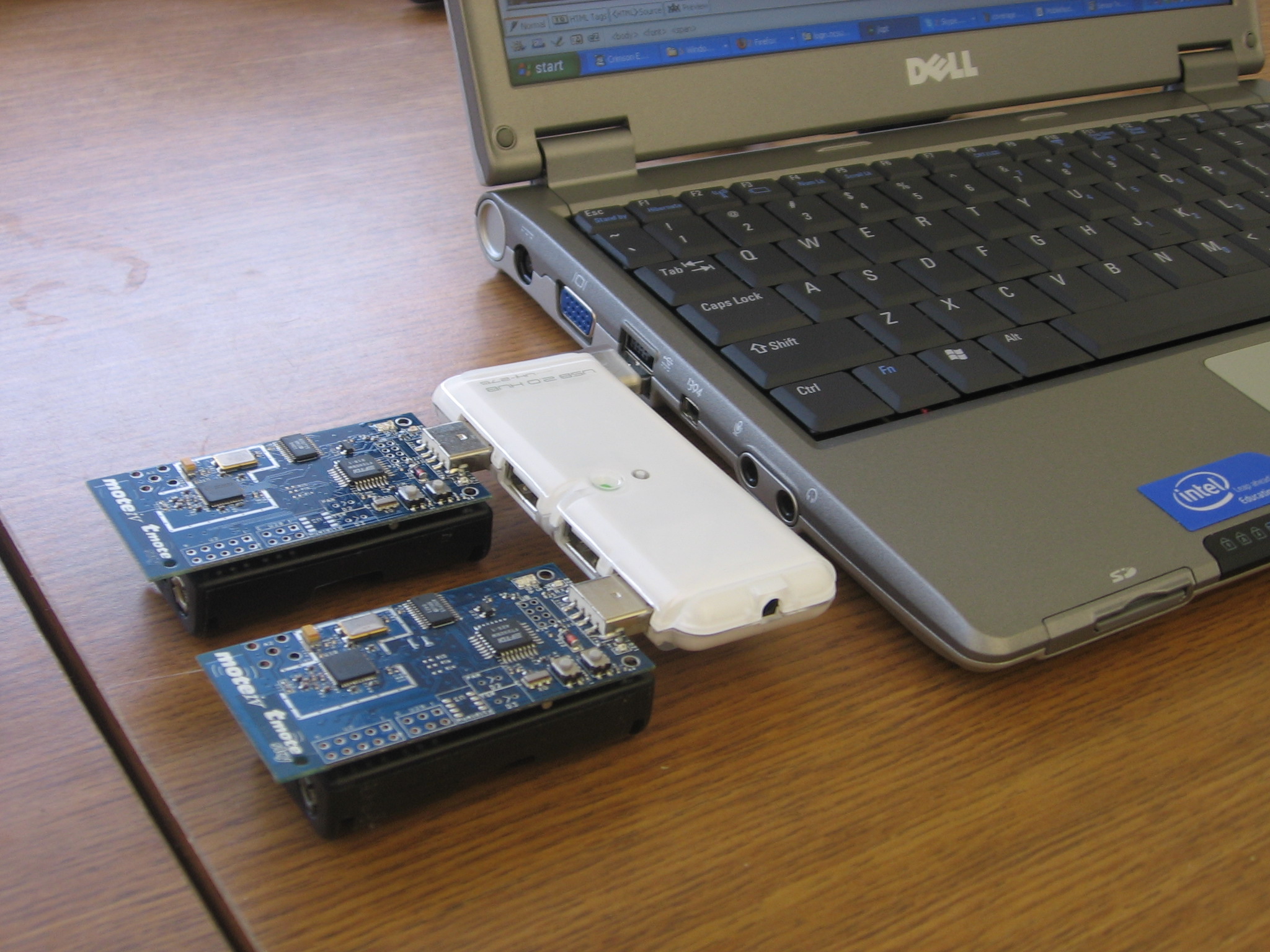 |
Here are the documents we used to configure Tmote Sky. We have installed Boomerang 2.0.4 software which is fully compatible with existing TinyOS 1.x application. Boomerang is a complete setup that installs the Tnote development tools (TinyOS 1.x, Java 1.5 JDK, nesC, cygwin (for windows), Graphviz, etc.), USB driver to access Tmote as a virtual COM port, and motiv's networking application tools. |
1. PIR Sensor
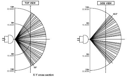
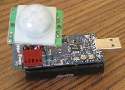
For motion detection, we connect a passive infrared (PIR) motion sensor to Tmote Sky. PIR sensor detects changes in infrared radiation which occur when there is movement by a person (or object) which is different in temperature from the surroundings. As sensor detects temperature differences, it is well suited to detecting the motion of people by their body temperature. We have configured an analog (Parallax #555-28027) and a digital (Panasonic AMN44121) sensorfor our testbed.
 Parallax (#555-28027) (~6m range) 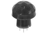 Panasonic AMN44121(~10m range) |
 |
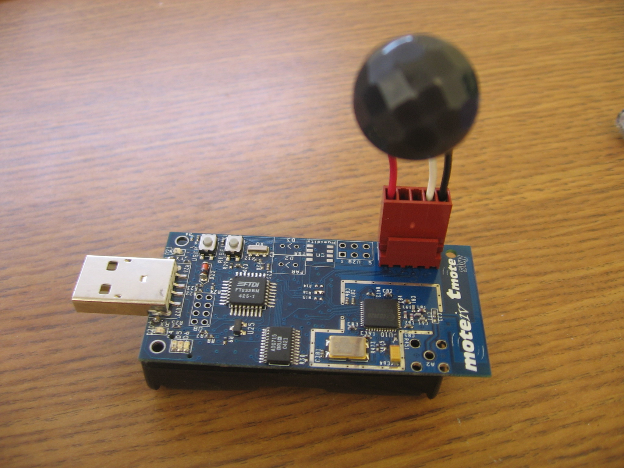
1.1 Connecting Analog
|
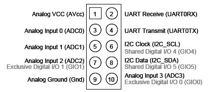
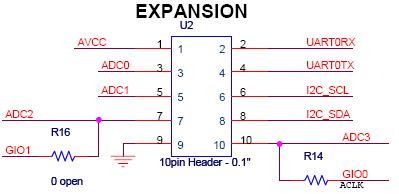
To connect an external analog sensor to Tmote we use the 10-pin expansion connector on tmote board. We connect our PIR sensor output to expansion pin 3 (ADC0). TOS_ADC_PIR_PORT = unique("ADCPort"), TOSH_ACTUAL_ADC_PIR_PORT = ASSOCIATE_ADC_CHANNEL( INPUT_CHANNEL_A0, REFERENCE_VREFplus_AVss, REFVOLT_LEVEL_2_5) |
| configuration AnalogPIRSendC { } implementation { ... components ADCC; Main.StdControl -> AnalogPIRSendP; Main.StdControl -> ADCC; AnalogPIRSendP.CommControl -> Comm; AnalogPIRSendP.SendMsg -> Comm.SendMsg[AM_OSCOPEMSG]; ... AnalogPIRSendP.ADC -> ADCC.ADC[TOS_ADC_PIR_PORT]; AnalogPIRSendP.ADCControl -> ADCC; } implementation { ... event result_t Timer.fired() { return call ADC.getData(); } async event result_t ADC.dataReady( uint16_t data ){ struct OscopeMsg *pack; atomic{ pack = (struct OscopeMsg *)msg[currentMsg].data; pack->data[packetReadingNumber++] = data; readingNumber++; ... if (packetReadingNumber == BUFFER_SIZE) post dataTask(); } m_int = data; return SUCCESS; |
1.2 Connecting Digital PIR Sensor to Tmote
 |
To use the external digital sensor in Tmote we connect our PIR sensor output to expansion pin 7 (GIO1). Since PIR (AMN44121) is low current consumption (digital output), 10 m detection, 3V DC type, we used one of the exclusive digital I/O port. One important detail, specified in the datasheet is that: -- If expansion pin 7 or 10 is used for digital I/O instead of analog inputs, R16/R14 must be populated with a 0 ohm resistor to enable GIO1/GIO0. |
After we connected the PIR sensor to the digital I/O pin 1, we use MSP430GeneralIO interface to get the output from sensor. An important detail is that GIO1 is designed to have interrupt capability. Thus, we catch up the motion by the voltage change in the output of PIR sensor triggers an interrupt. Here is some useful information to get output using GIO1.
- use TOSH_MAKE_GIO0_INPUT();
-
wire ReadPIRP.PIR -> MSP430GeneralIOC.Port21;
ReadPIRP.PIRInput -> MSP430InterruptC.Port21; -
set ADC2 as input by putting the macros TOSH_MAKE_ADC3_INPUT(); (output by default)
| components
Main; components ReadPIRP; components MSP430GeneralIOC; components MSP430InterruptC; ... Main.StdControl -> ReadPIRP; ReadPIRP.PIR -> MSP430GeneralIOC.Port21; ReadPIRP.PIRInput -> MSP430InterruptC.Port21 module ReadPIRP { provides interface StdControl; uses interface Leds; uses interface MSP430GeneralIO as PIR; uses interface MSP430Interrupt as PIRInput; } command result_t StdControl.init() { TOSH_MAKE_ADC2_INPUT(); TOSH_MAKE_GIO1_INPUT(); return SUCCESS; } async event void PIRInput.fired(){ .... } |
1.3 Digital versus Analog PIR
After configuring analog and the digital sensors, we decide to extend our test-bed using analog PIR sensors. A comparison will be available between analog and digital PIR in terms of computability to Telos.
Technical Documents
An Example Application and Initial Results
Application specific configuration and results will be available soon.
Related Publications
1. Health-Care Applications of Wireless Sensor Networks
- Ultrasonic Sensors for the Elderly and Caregivers in a Nursing Home, Toshio Hori, Yoshifumi Nishida, ICEIS, 2005.
- Wireless Sensor Networks for In-Home Healthcare: Potential and Challenges, J. A. Stankovic, Q. Cao, T. Doan, L. Fang, Z. He, R. Kiran, S. Lin, S. Son, R. Stoleru, A. Wood, HCMDSS, 2005.
- Towards Activity Databases: Using Sensors and Statistical Models to Summarize People's Lives, Tanzeem Choudhury, Matthai Philipose, Danny Wyatt, Jonathan Lester, Data Engineering Bulletin, 2006.
- Sensor Networks for Medical Care, Victor Shnayder, Borrong, Chen, Konrad Lorincz, Thaddeus R. F. FulfordJones, and Matt Welsh, Tech. Report, Harvard University, 2005.
- Inventing Wellness Systems for Aging-in-Place, Eric Dishman, Intel Research, 2004.
- Improving Patient Monitoring and Tracking in Emergency Response, Tia Gao, Dan Greenspan, and Matt Welsh. In Proceedings of the International Conference on Information Communication Technologies in Health, July 2005.
- Use of Wireless Technologies for Assisted Living at Home, Mobiquitous 2005.
- UF SMART HOME DEMONSTRATES CONCEPT OF AUTOMATED ELDERLY HELP AND CARE.
2. In-door, Home Wireless Sensor Networks
- Experimental Characterization of Home Wireless Networks and Design Implications, K. Papagiannaki, M. Yarvis, and W. S. Conner, in IEEE Infocom, Barcelona, Spain, April, 2006.
- A Survey of Research on Context-Aware Homes, Sven Meyer and Andry Rakotonirainy, WICAPUC, 2003.
- Simplified Simulation Models for Indoor MANET Evaluation are not Robust, Andres Lagar Cavilla, Gerard Baron, Thomas E. Hart,Lionel Litty and Eyal de Lara, Secon 2004.
3. Other Experimental Studies for Wireless Sensor Networks
- Energy-Efficient Surveillance System Using Wireless Sensor Networks, Tian He, Sudha Krishnamurthy, John A. Stankovic, Tarek Abdelzaher, Liqian Luo, Radu Stoleru, Ting Yan, Lin Gu, MobiSys, 2004.
- Complex Behavior at Scale: An Experimental Study of Low-Power Wireless Sensor Networks, Deepak Ganesany, Deborah Estrin, Alec Woo, David Culler, Tech. Report, UCLA, 2002.
- An Experimental Study of Routing and Data Aggregation in Sensor Networks, Ossama Younis, Sonia Fahmy, MASS 2005.
- Lightweight Detection and Classification for Wireless Sensor Networks in Realistic Environments, Lin Gu, Dong Jia, Pascal Vicaire, Ting Yan, Liqian Luo, Ajay Tirumala, Qing Cao, Tian He, John A. Stankovic, Tarek Abdelzaher, Bruce H. Krogh, SenSys, 2004.
- Experimental Evaluation of Synchronization and Topology Control for In-Building Sensor Network Applications, W. Steven Conner, Jasmeet Chhabra, Mark Yarvis, Lakshman Krishnamurthy, WSNA, 2003.
- Experimental study of the effects of Transmission Power Control and Blacklisting in Wireless Sensor Networks, Dongjin Son, Bhaskar Krishnamachari, and John Heidemann, Secon 2004.
- Experimental Study of Concurrent Transmission in Wireless Sensor Networks, Dongjin Son, Bhaskar Krishnamachari, John Heidemann, SenSys 2006.
- VigilNet: An Integrated Sensor Network System for Energy-Efficient Surveillance, Tian He, Sudha Krishnamurthy, John A. Stankovic, Tarek Abdelzaher, Liqian Luo, Radu Stoleru, Ting Yan, Lin Gu, TOSN, 2006.
- FireWxNet: A MultiTiered Portable Wireless System for Monitoring Weather Conditions in Wildland Fire Environments, ACM MobiSys 2006.
- Understanding packet delivery performance in dense wireless sensor networks, J. Zhao and R. Govindan, in Proc. of ACM Conference on Embedded Networked Sensor Systems (SenSys), Los Angeles, CA, Nov. 2003.
Useful Links
If you have any question, please feel free to contact Nurcan Tezcan or Kaseima Frye.