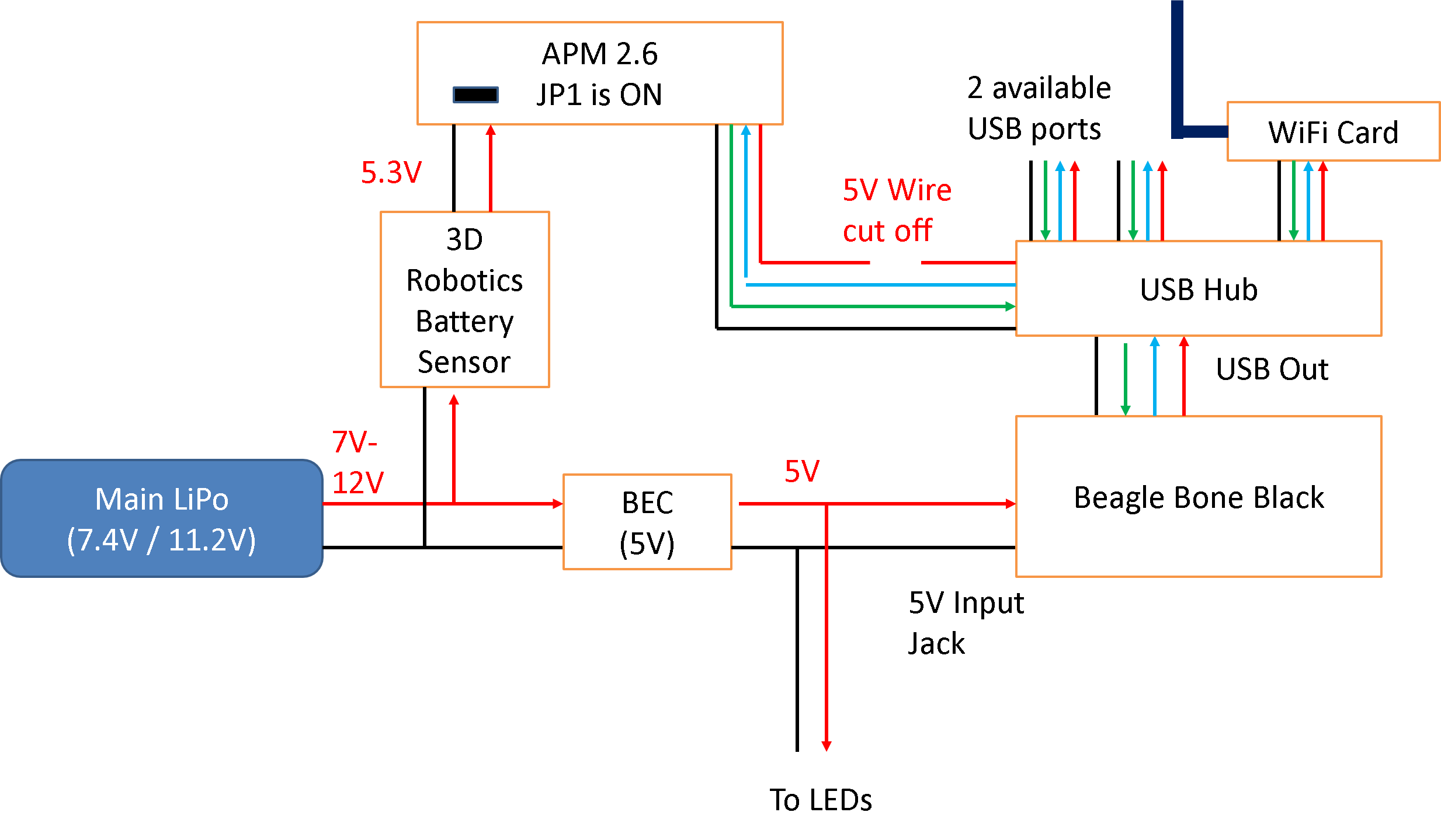
The main problem with the current setup is that the autopilot of choice requires 5.3V as voltage input (as it uses a protection diode that drops the extra 0.3V). This conflicts with the USB power output of 5V (apparently to the same point in the schematic - Vcc). Therefore, the two choices to be made are to
- either power everything from 5V, but that would be dropped to 4.7V in the autopilot, which may cause brownouts,
- or to eliminate the USB power (by cutting the 5V wire in the USB cable). This is the current powering scheme, shown below.

IMPORTANT NOTE
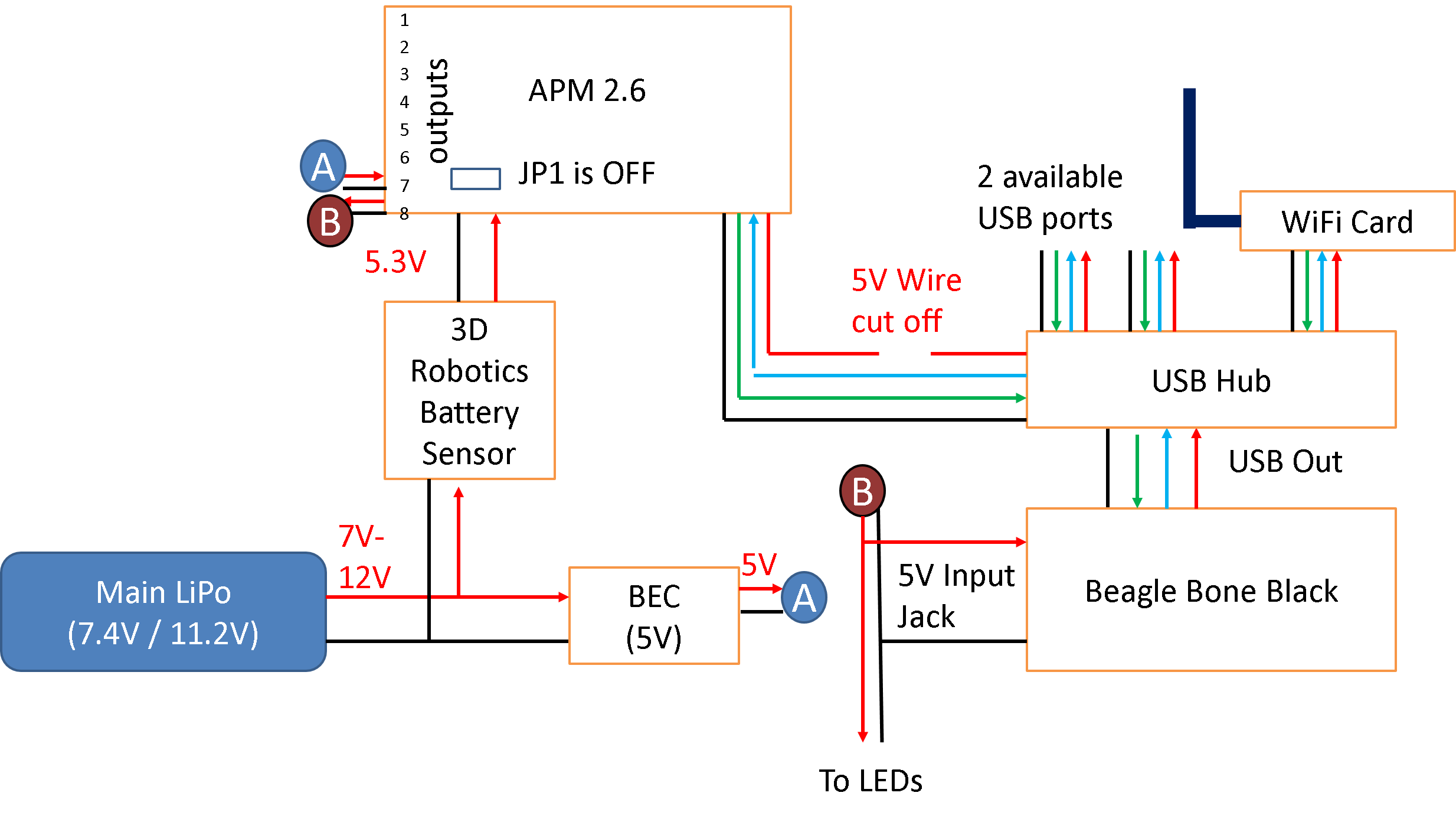
JP1 in APM 2.6 is in OFF position. Removing the jumper allows you to use the APM’s servo output rail to distribute power from your separate UBEC to external equipment viz. BeagleBoneBlack and LEDs. If for some reason, you would prefer to have the jumper JP1 as ON, then kindly refer to dronePowerSetupAlternate.png for power distribution.
Last modified 23 months ago
Last modified on Jan 15, 2014, 5:56:05 AM
Attachments (6)
- dronePowerSetup.png (79.6 KB) - added by mlsichit 2 years ago.
- dronePowerSetup.pptx (51.5 KB) - added by mlsichit 2 years ago.
- dronePowerSetup.2.png (134.6 KB) - added by vananth2 23 months ago.
- dronePowerSetupAlternate.png (56.2 KB) - added by vananth2 23 months ago.
- dronePowerSetupAlternate.pptx (36.2 KB) - added by vananth2 23 months ago.
- dronePowerSetup.2.pptx (36.9 KB) - added by vananth2 23 months ago.
Download all attachments as: .zip